Showing posts with label Gas Turbine Generator. Show all posts

Working Principle of Gas Turbine


The working principle of gas turbine is to convert the chemical energy of fuel into mechanical energy through combustion process, and then the mechanical energy is converted by a generator into electrical energy. Gas turbine works with Brayton cycle and its working fluid is gas. The simplest gas turbine system consists of 3 (three) main components: compressor, combustor and turbine, with the arrangement as shown in Figure 1.
Figure 1: Working Principle of Gas Turbine Diagram

The working principle of gas turbine system is the atmospheric air goes into the compressor which serves to suck air and raise the pressure of air, so that its pressure will rise. Then the high pressure air flow into combustion chamber. In the combustion chamber the fuel is sprayed into the air flow, resulting in the burning/combustion process. The combustion process takes place at constant pressure, so it can be said that the combustion chamber is used only to raise the temperature of air. High-temperature combustion gas is then entered into a gas turbine in which its energy is used to rotate turbine blades. As much as ± 60% of power generated by turbine is used to rotate compressor itself, the remainder is used to turn generator.

This ideal cycle consists of 2 (two) Isobars processes that occur in the combustion chamber and exhaust process of used gases, and 2 (two) isentropic processes that occur in the compressor and the expansion of gases in the turbine.
Figure 2: Brayton Cycle
Figure 3: P-V Diagram of Gas Turbine 
The working principle of gas turbine process can be explained as follows:

Stage 1-2: This stage is isentropic compression process is in the compressor, condition 1 is the atmosphere air. Temperature of compressed air (T2) can be determined from the relationship of:
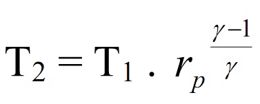
where:

rp = ratio of pressure  P2/P1
γ = ratio of specific heat at constant pressure and specific heat at constant volume, for air γ = 1.4

Stage 2-3: This stage is the process of adding heat at constant pressure in the combustion chamber. Heat is added to the combustion chamber is:

Qin = Cp (T3 – T2)

Stage 3-4: This stage is isentropic expansion process in the turbine. The exit gas temperature (T4) is calculated by the relationship of:

Stage 4-1: This stage is the process of releasing heat to the surroundings at constant pressure. The amount of heat released is calculated by the following formula:

Qout = Cp (T4 – T1)

Working net of gas turbine (Wnet) is a useful work produced by the turbine after expansion work is reduced by the work of compression. Amount of working net of gas turbine is:

Wnet   = WT – WK
= (h3 – h4) – (h2 – h1)

Net power turbine is the turbine output power (generator power needed) after considering the losses, the net power turbines are:

Pnet = mg .WT – mg . WK

Cycle efficiency of working principle of gas turbine is the ratio between the amounts of effective heat with the heat that is inserted into system, namely:

READ MORE - Working Principle of Gas Turbine

Gas Turbine Cycle


Gas turbine cycle is one of thermodynamic cycle processes. Rankine cycle uses steam as the working fluid. The Rankine cycle performance control is formed by the percentage of the existing highest and lowest cycle temperatures. The existing highest steam temperature in a Rankine cycle is about 1100 F (594 C), which usually is established mainly by material restrictions at the increased pressures of the cycles of steam. Just one indicates of advancing the performance control is to change the working fluid by using gas or air.
Figure 1: Gas Turbine Cycle

The gas turbine cycle process in the most basic form contains a turbine, combustor and also compressor as shown in Figure 1. Due to its simpleness, low budget fee and quick lead time period, gas turbine is now being applied by several utilities to increase capability in smaller batches. Utilization of the gas turbine cycle process in combination with Rankine cycle which uses steam can be an efficient indicates of recuperating several heat lost as soon as combustion gases are discharged to the environment at excessive temperatures.

In the basic gas turbine cycle process as demonstrated in Figure 1, air is pressurized then combined together with fuel and also burnt in the combustor. The gaseous combustion items which have high temperature get into turbine to generate work through expansion. A part of the work generated by turbine is utilized to generate the compressor and the rest is obtainable to generate power. The exhaust gases of turbine are subsequently vented to the environment. To assess the cycle, some simplifying suppositions are created.

First, however the process of combustion alters the working fluid arrangement, the fluid is addressed as a gas of individual arrangement all through, and it's deemed an suitable gas to get basic relationships among points in the process. Second, the process of combustion is assumed as a uncomplicated heat transfer process where the heat enter to the working fluid is established by the heating values of fuel. A outcome of this estimation is that the flow rate of mass as a result of the process stays consistent. The final estimation is to suppose that every of the functions which can be reversed internally.

When the expansion of turbine is finished with the exhaust gas at the similar pressure as the inlet air of compressor, the collaboration of operations could be considered as a cycle. The simple suppositions above provide the perfected gas turbine cycle known as air common Brayton cycle. Figure 2 below displays the cycle on P-v and Ts diagrams that allow identifying the condition parameters at the several cycle areas.
Figure 2: Brayton Cycle


READ MORE - Gas Turbine Cycle

Gas Turbine Generator


Gas turbine generator is turbine generator that uses gas as the working fluid. The simplest gas turbine generator system consists of three main components: compressor, combustion chamber, and gas turbine as shown in Figure 1.  Ideal cycle of simple gas turbine generator system is Brayton cycle.
Figure 1: Brayton Cycle of Gas Turbine Generator

The working principle of gas turbine generator system is atmospheric air enter into the compressor which serves to suck and increase air pressure, so that its temperature will rise. Then the air-pressure and high temperature is entered into combustion chamber. In the combustion chamber the fuel is sprayed into air flow, resulting in burning / combustion process.

The combustion process takes place at constant pressure, so it may be said that the combustion chamber is used to raise air temperature. Therefore combustion chamber could be replaced with a heater. High-temperature combustion gas is then entered into gas turbine where its energy is used to rotate turbine blades. As many as 60% of power that is generated by turbine is used to rotate the compressor itself, the rest is used to turn generator.
Figure 2: T-S Diagram of Gas Turbine Generator

In accordance with Figure 1 and Figure 2 above, Brayton cycle can be described as follow:

Stage 1-2 : The process of isentropic compression in the compressor.
Stage 2-3 : The process of heat inclusion or heating  at constant pressure in the combustion chamber.
Stage 3-4 : The process of isentropic expansion in gas turbine generator.
Stage 4-1 : The process of disposal heat at constant pressure in heat exchanger equipment.

From figure Brayton cycle and T-S diagram above it would be taken assumption that the cycle is steady state, the difference in potential energy and kinetic energy is ignored because of too small, so the equation can be obtained as follow:

(qin - qout) + (win - wout) = houtlet – hinlet

where:
qin = h3 - h2 = Cp (T3 - T2)
qout = h4 - h1 = Cp (T4 - T1)

so that thermal efficiency of brayton cycle can be obtained as follow:

Stage 1-2 and 3-4 are isentropic process where P1 and P2 = P4 = P1 so that:

The equation above can be substituted into equation form of simpler thermal efficiency as follow:

READ MORE - Gas Turbine Generator

Gas Turbines for Power Generation


Gas turbines for power generation has working principal that is started when the air enter into compressor through air inlet. Compressor serves to suck and raise the air pressure and consequently raise the air temperature too.

Then, this air that has compressed enters into the combustion chamber. Fuel is sprayed into combustion chamber so that the fuel is mixed with air and causes the burning process occurs. The combustion process takes place in a state of constant pressure so that it can be said combustion chamber simply to raise the temperature.

Gas from combustion process is supplied to gas turbine through nozzle that serves to direct the flow of gas to turbine blades. Power that is generated by gas turbines is used to rotate compressor and run other loads such as electric generators, etc.  After passing through this turbine, gas will be discharged through the exhaust. At this the cycle of gas turbines for power generation is completed.

READ MORE - Gas Turbines for Power Generation